|
<< Click to Display Table of Contents >> Manual wire-numbering |
  
|
|
<< Click to Display Table of Contents >> Manual wire-numbering |
  
|
In most cases, it is best to use automatic wire-numbering to a greater or lesser extent to speed up the work. For various reasons, it is however possible to number a complete project, or part of a project, manually from start.
To aid manual wire-numbering, you have access to an unlimited number of counters in the Drawing Environment, of which 16 are predefined. These will help you remember the last used wire-number for each counter. You can therefore work simultaneously with an arbitrary number of counters.
You choose the Wire-number command, which you will find in the Symbol Insert Tool, in the Cables resource category.
This command, which you use to perform a manual wire-numbering, will be described in more detail in the Drawing Environment topic. Here, however, a comprehensive description of it is provided.
In the command line, you will get the following prompt:
Choose connection point (point, cancel with <RETURN>):
You should first select the first connection point in the node which you are about to wire-number. This selection is done with the ENDPoint object snap. The wire-number should be inserted exactly on the connection point for the symbol which the wire comes from. Therefore, you should click on the line which connects to the connection point in question. Please note that each line has two ends, as does a sausage (!). Therefore, you should click close to the correct end of the line, the one that connects to the connection point where the first wire originates.
The wire-number symbol is automatically inserted with an appropriate orientation.
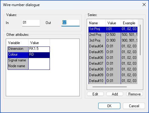
Thereafter, you will be presented with a dialogue where you can specify the ingoing and outgoing wire-numbers for the connection point in question, and the properties for the outgoing wire (dimension, colour, node name and signal name).

Figure 1719: Dialogue for wire-numbers
You can also choose any of the counters, which have already been mentioned. You do that in the right part of the dialogue.
All counters are completely free, meaning that you can freely control start and step values. The first three counters are initially tied to the numbering series, which are defined by the project parameters, meaning that they have borrowed their start and step values from them. (Please refer to the Number series sub-topic of the Project module topic). It is, however, up to you to change those values if you like. It is also possible to create other counters, others than the 16 which are defined from the beginning. And you can also change the names of the counters to whatever you like.
You have three buttons available under the list with the counters. With the Edit button, you can change the selected counter, meaning its name, its start value, and its step value. With the Add button, you create a new counter, and with the Remove button, you remove a selected counter completely.
Select any of the counters by clicking it. In- and outgoing wire-numbers will then be fetched from the selected counter. If you have done this correctly, and you start a new wire-chain, the ingoing wire-number is empty.
Make desired changes concerning in- and outgoing wire-number, and connection properties. Accept your changes with the OK button.
The prompt that requests you to select a connection point, will re-appear. Click on the next connection in the node, in a similar manner, meaning on the corresponding line.
The dialogue will also re-appear. Now you have both ingoing and outgoing wire-numbers. Accept and continue with further connection points within the node.
Be careful with the sequence. You should define the connection points in the same order as you wish to have for the physical wiring.
When you have reached the final connection point in the node, it is important that you finish the “wire-chain”. You do this in the dialogue for the final connection point by removing the outgoing wire-number. You would otherwise get a wire-number pointing to nowhere.
To the right in the dialogue box, you can always see where you currently are for the counter in question. You see the next wire-number for the counter, and a letter. I specify ingoing and O outgoing wire-numbers.
The number series you are currently using is marked with a deviating colour.
A short summary of how you perform manual wire-numbering is provided in the following sub-topic:
•Summary manual wire-numbering.