|
<< Click to Display Table of Contents >> Basic principle |
  
|
|
<< Click to Display Table of Contents >> Basic principle |
  
|
The lines in a circuit diagram define which connection points are connected with one another. Connection points that are connected are said to belong to the same "sub-node" or "wire-chain". If we disregard cables, the connection points are connected with wires in a chain, a so-called wire-chain. Please refer to the Basic concepts topic for a further explanation of these terms and concepts.
Example:
We have three connection points named 1, 2 and 3, which are connected with one another, like in the figure below.
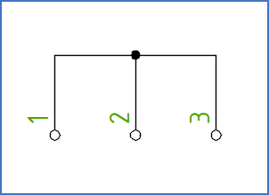
Figure 1438: Three connection points that are connected in the same sub-node (wire-chain)
To connect three connection points, we need two wires. These wires can be connected in three different ways:
Possibility |
Wiring sequence |
|---|---|
1 |
1 - 2 - 3 |
2 |
2 - 3 - 1 |
3 |
3 - 1 - 2 |
If we also consider wiring directions, so that 1 - 2 - 3 is not regarded as identical with 3 - 2 - 1, we have six possibilities.
If the number of involved connection points increases, the number of possible ways to connect them increases even more. (With 4 connection points, you have 24 possibilities, with 5 connection points 120, and with 6 connection points no less than 720 different ways of connecting the wires. These numbers quickly reach almost unimaginable levels. 10 connection points can be connected in 3 628 800 ways, and 20 connection points in no less than 2.4 quintillion ways).
Wire-number symbols are used to define the wiring sequence. They are also used to define wire-numbers, meaning individual numbers for each wire. Finally, the wire-number symbols may contain information about the properties of the wires, like colours and dimensions.
Wire-number symbols are inserted in a circuit diagram manually, automatically or in a combination of both. They are placed at the connection points of the symbols.
Each wire-number symbol contains three attributes, as described by the table below.
Attribute |
Explanation |
Placement for vertical lines |
Placement for horizontal lines |
|---|---|---|---|
Wire-number in |
The wire-number of a wire that ends in the connection point in question
|
To the left of the line |
Above the line |
Wire-number out |
The wire-number of a wire that starts in the connection point in question
|
To the right of the line |
Below the line |
Properties out |
The properties of a wire that starts in the connection point in question
|
Invisible |
Invisible |
The figure below shows wire-numbers in a simple vertical circuit diagram. On the right side of the lines, you will find wire-numbers for outgoing wires. On the left side of the lines, you will find wire-numbers for ingoing wires.
Please note that the wiring sequence is different if you compare the upper and lower sides of the symbols in the figure. The table below the figure shows a simplified wire-list generated from the diagram.
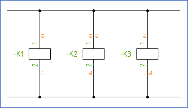
Figure 1439: Wire-numbers in a vertical circuit diagram
Wire-number |
From |
To |
|---|---|---|
01 |
-K1:1 |
-K2:1 |
02 |
-K2:1 |
-K3:1 |
03 |
-K1:2 |
-K3:2 |
04 |
-K3:2 |
-K2:2 |
The figure below shows a similar example, but for a horizontal circuit diagram. In this case, you find wire-numbers for outgoing wires below the lines. Above the lines, you will find wire-numbers for ingoing wires.
The table below the figure shows a simplified wire-list generated from the diagram.
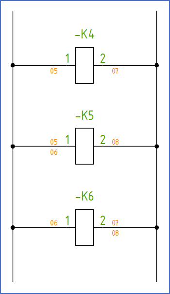
Figure 1440: Wire-numbers in a horizontal circuit diagram
Wire-number |
From |
To |
|---|---|---|
05 |
-K4:1 |
-K5:1 |
06 |
-K5:1 |
-K6:1 |
07 |
-K4:2 |
-K6:2 |
08 |
-K6:2 |
-K5:2 |
The interpretation of both circuit diagrams presented above is shown in the wire-lists. To further clarify how this works, the figure below contains a graphical representation of this interpretation.
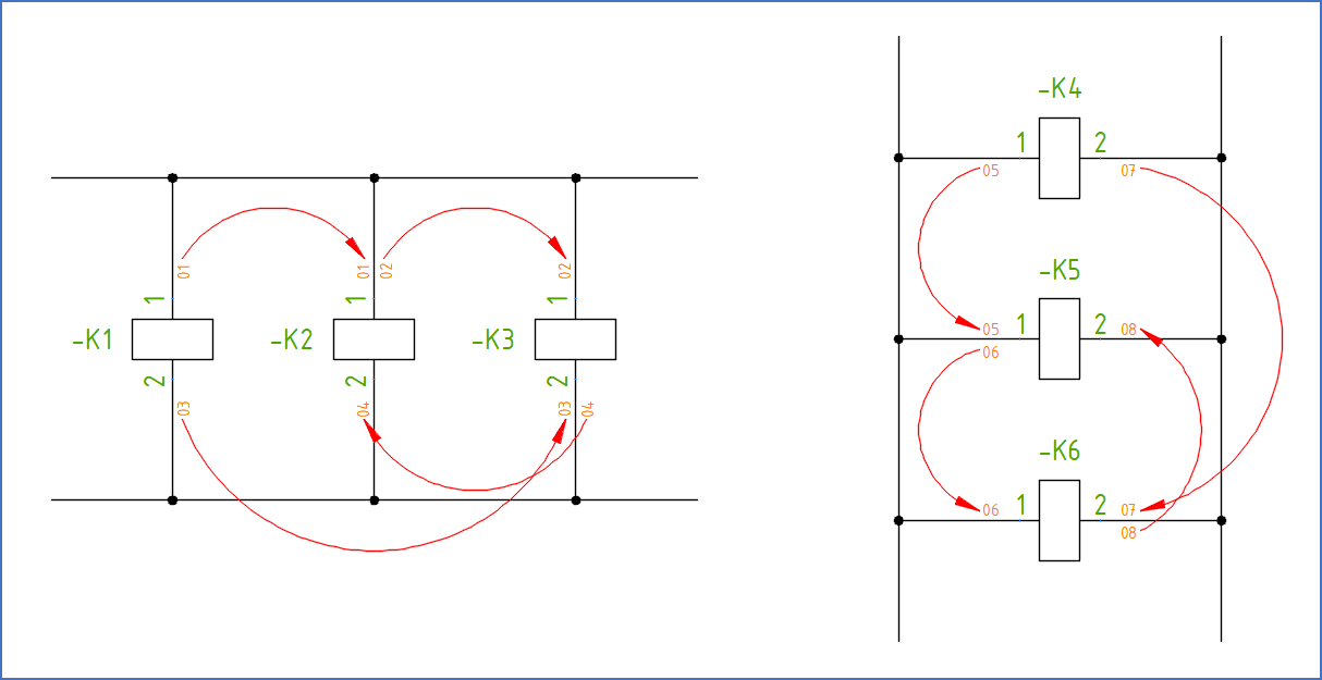
Figure 1441: Interpretation of the wire-numbers in the two figures above
Besides the three attributes discussed above, the wire-number symbols also contain a graphical POINT placed in the INDEX layer. This POINT is placed in the insertion point of the wire-number symbol. The wire-number symbol has its insertion point on a connection point of a conventional symbol.
For terminals, the wire-number symbols will have their insertion points in the end of the connecting lines or in other words where the connecting lines meet the graphical circle. Please refer to the figure below.
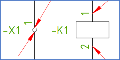
Figure 1442: The placement of wire-number symbols