|
<< Click to Display Table of Contents >> Allow forced connections |
  
|
|
<< Click to Display Table of Contents >> Allow forced connections |
  
|

Figure 492: The "Allow forced connections" check-box
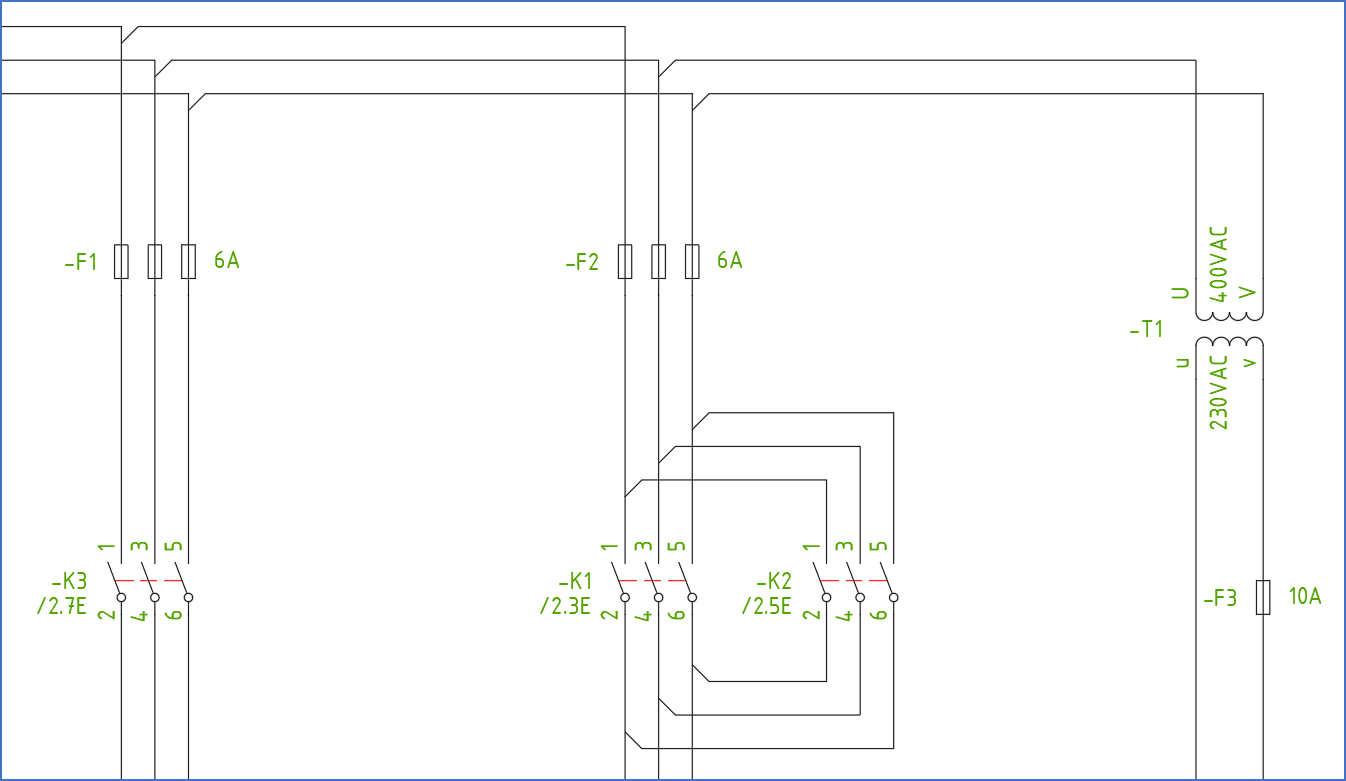
Forced connections means that the wiring sequence is assigned in the circuit diagram using lines in a 45º angle.

Figure 493: This figure shows a section of a drawing sheet with so-called "forced connections".
A circuit diagram drawn with forced connections is strictly speaking rather a connection diagram.
Nevertheless, forced connections are still common in several places around the world. In Germany, where this method was first invented, it is a commonly used documentation method. The circuit and connection diagrams are there combined to one single document, which both describes the function - as a circuit diagram should - and the connections - as a connection diagram should.
The set of rules that apply to the use of forced connections, are described elsewhere.
The Allow forced connections project parameter controls whether the electrical lines of the circuit diagrams should be scanned for possible forced connections, and interpreted as such when applicable.
•If this parameter is deactivated, it does not matter for the connection processing if lines are drawn in an angle. The interpretation will be the traditional one, where cabinet layout and item designations control the wiring order, until wire-numbers are inserted and take control.
•If the parameter is activated, however, forced connections (lines in angles) will control the wiring order, as long as there are no wire-numbers present. If there are, wire-numbers will have priority over forced connections.
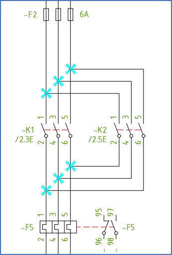
Please note that the rules that apply for forced connections forbid lines to meet in a "T". Any deviation from these rules will be interpreted as an error and reported as such in the OnLine Protocol. A circuit diagram drawn in a conventional way will therefore be considered as having a large number of errors if Allow forced connections has been activated. Each electrical node which contain forced connection errors, will be analysed using the traditional set of rules that apply when forced connections are deactivated. The forced connection analysis will, in other words, be turned off for each node where forced connection errors occur. If this parameter is not activated, all forced connections (45º angles) will be ignored.

Figure 494: This figure shows a section of a conventional circuit diagram with warnings for forced connection errors in "T-connections".