|
<< Click to Display Table of Contents >> Specify insertion point |
  
|
|
<< Click to Display Table of Contents >> Specify insertion point |
  
|
The insertion point of a cadett ELSA symbol is defined by a Symbol object. Please refer to the Symbol Generator Objects topic.
Specifying the insertion point of a symbol is something that you will have to do, only when you create a symbol from scratch. If you create a symbol by editing an existing symbol, the insertion point is already defined. In that case, there might be a need to adjust the insertion point, but not to specify it in the way you do when you create a new symbol. Here we will discuss the procedure to define the insertion point for a new symbol, which does not have an insertion point defined already.
If no Symbol object is available when you click the OK button in the Symbol data dialogue box, you will be asked to specify the insertion point.
•If you are editing an existing symbol, the Symbol object will already be present, and you will not be asked to specify the insertion point.
•If you are creating a new symbol, no Symbol object will be present, and you will be asked to specify the insertion point. The insertion point is defined by the Symbol object, which will be inserted at that time.

Figure 858: The prompt to specify insertion point
In the command line, you will be prompted to specify the insertion base point of the symbol, as shown in the figure above.
In the IEC1082 standard symbol library, the insertion point for vertical symbols is typically placed in the lower left connection point. For horizontal symbols, it is instead placed in the upper left connection point.
In the new IEC1714 standard symbol library, the insertion point is instead placed in the middle between the first two connection points.
When you create your own symbols, you are free to decide for yourself where you want to place the insertion point. Our general advice is to be as consistent as possible.

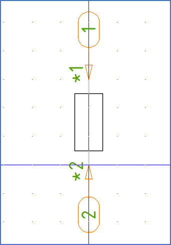
Figure 859: Here, the insertion point is placed in the lower left connection point, to be consistent with standard symbols in the IEC1082 symbol library.
When you left-click in the desired position, the symbol object will be inserted in that very position.
The attribute package that you have defined in the Symbol data dialogue, will also be inserted, but in a standard position that you almost always will have to adjust, more or less.
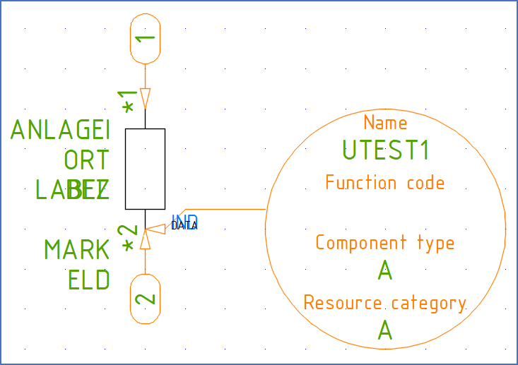
The figure below shows how it might look, directly after you have placed the insertion point.

Figure 860: The insertion point has been defined with a Symbol object that points at it.
Sometimes, the Symbol object may end up in an unfavourable direction, on top of other objects, which will make it difficult to read the information in it. many times, you can solve that problem by rotating the Symbol object somewhat. You do that using the ROTATE command, which you find in the ribbon menu, Home tab, Modify slide-out panel.

Figure 861: The Symbol object has been rotated for better visability.
When you are satisfied with the position and direction of the Symbol object, it is time to adjust positions, text justifications, and other properties of the attributes. Please refer to the Adjusting attributes topic.