|
<< Click to Display Table of Contents >> No graphics check-box |
  
|
|
<< Click to Display Table of Contents >> No graphics check-box |
  
|
The No graphics check-box is available when creating new I/O's only. When editing existing ones, it is greyed out. The description below therefore deals with new I/O's only.
If you do not check No graphics, you will get graphics! This means that by default, you will get not only the connection point numbers, and the other needed attributes defined, but also the graphics drawn for you. After all, the I/O's in a PLC mirror should in most cases look the same, so why not?
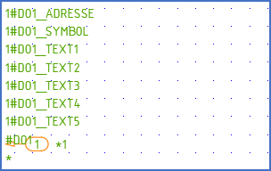
On the other hand, if you for one reason or the other do not want to use one of the standard appearances of the I/O's, you can check the No graphics check-box. If you do, you will insert a function object with connection point numbers, a cross-reference, and the other needed attributes, but no graphics. You will then have to draw the graphics yourself.

Figure 1079: This is a horizontal digital output, 1 connection point, with graphics. The arrow points at the position of the cross-reference, which needs to be adjusted here.

Figure 1080: This is a vertical digital output, 1 connection point, without graphics. The arrow points at the position of the cross-reference.