|
<< Click to Display Table of Contents >> The columns of the terminal list |
  
|
|
<< Click to Display Table of Contents >> The columns of the terminal list |
  
|
The contents of all columns in the terminal list of Dynamic OnLine I are described in full detail by the table below.
Column |
Description |
|---|---|
Terminal icon / wire/cable dim. |
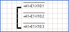
In this field, an icon is shown which symbolises the terminal as such, and the connection between the terminals in the terminal group. A black line connects the green and red icons within a terminal group with each other.
 Figure 1363: Terminal group
The green icon specifies terminals that are defined in the circuit diagram, regardless of whether they are connected or not.
Red icons specify spare terminals. Spare terminal are defined by a numbering algorithm and a limit.
 Figure 1364: Spare terminal
To the right of the above-described icon, the dimension for a possible internal connection from the current terminal is specified. For cable cores, this is the electrical data of the cable in question. For wires, this is the dimension which has been specified for those.
|
Designation (cable) |
If the connection on the internal terminal side is made up of a cable core, the complete item designation of the cable to which the cable core belongs is specified.
|
Wire-number |
If the connection on the internal terminal side is made up of a wire, thus not a cable core, and that wire has been assigned a wire-number, that wire-number will be displayed here.
|
Internal connection |
The complete item designation of the device to which the connection goes is shown here. If the connection goes to a terminal, the complete terminal group name will be shown.
|
Conn.point no. |
For devices, the connection point number to which the connection goes is shown here. For terminals, this is in a corresponding way the terminal number.
|
4:th internal link level |
Links are presented graphically in up to four levels, for which four columns on the internal side and four on the external side are available.
 Figure 1365: Simple internal link
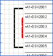
The link analysis can separate between so-called “short links” and “long links”. Short links are links connecting neighbouring terminals.
 Figure 1366: Long link (black) and short link (red)
In the terminal list of Dynamic OnLine I, the long links will be shown as “black forks”, while short links are shown as “red bars”.
Short links are presented in the terminal list of Dynamic OnLine I on the side which they are located. Reports which are created by the Report Generator, normally presents them in the middle, meaning neither internally nor externally.
How these short links should be calculated and presented is controlled by a setting in the Terminal list section. Show short links should therefore be activated or deactivated depending on whether you want to separate these kinds of links or not.
It is also possible to control the terminal lists which are created by the Report Generator in a corresponding way.
|
3rd internal link level |
See above.
|
2nd internal link level |
See above.
|
1st internal link level |
See above.
|
Terminal |
The complete item designation of the terminal, including both terminal group name and terminal number. This is only displayed once for each terminal, despite that each terminal occupies at least two sub-rows. On the last sub-row of a terminal, in most cases the second one, an underline will instead be displayed. That is a horizontal line in the lower edge of the field. This makes it as clear as possible where the terminal ends, and the other terminal begins.
|
1st external link level |
In this and the three following columns, the external links are shown in a graphical manner. See the description of the internal links above.
|
2nd external link level |
See above.
|
3rd external link level |
See above.
|
4th external link level |
See above.
|
External connection |
The complete item designation of the device to which the external connection from the current terminal goes. If it is connected to a terminal, the complete terminal group name is shown instead.
|
Conn.point no. |
For devices, the connection number to which the connection goes is shown. For terminals, the terminal number is shown instead.
|
Wire/cable dim. |
Here, the dimension for any possible external connection from the current terminal is shown. For a cable core, this is the electrical data for the cable in question. For a wire, this is the dimension which has been specified for that.
|
Designation (cable) |
If the current external connection is made up of a cable core, the item designation of the cable to which the cable core belongs, is shown here. For wires, nothing is shown here.
|
Wire-number |
For connections which have been assigned wire-numbers, that number is shown here. Please note that you can have cable cores which nevertheless also have wire-numbers. Such connections have cable core numbers and wire-numbers simultaneously, in parallel. This is for example the case, when using wire-number binding. (Please refer to the Wire-number binding topic).
|
Sh. ref. |
A cross-reference to the current terminal, in accordance with currently defined composition in the project, is shown. It is a reference to the position in a specific drawing sheet where the symbol for the current terminal resides.
|
Remark |
A possible remark for the current terminal is presented in this column.
|
Parent |
For terminals which inherit their terminal group name and index from the previous terminal, which by the way is very common, a specification of the parent terminal from which the information is inherited is shown. If this field is empty, the terminal does not inherit information, meaning that the terminal group name and the index originates from the symbol of the terminal itself.
|